Extreme Loading® for Structures

Extreme Loading® for Structures Software or ELS, is an advanced non-linear dynamic structural analysis software tool designed with the practicing structural engineer in mind. ELS allows structural engineers to study the 3D behavior of structures through both the continuum and discrete stages of loading. This includes static and dynamic loads such as those generated by blast, seismic events, impact, progressive collapse, and wind. ELS utilizes a non-linear solver based on the Applied Element Method (AEM) a derivative of the Finite Element Method (FEM) and the Discrete Element Method (DEM). This allows ELS is to automatically analyze structural behavior during elastic and inelastic modes including the automatic yielding of reinforcement, detection and generation of plastic hinges, buckling & post-buckling, crack propagation, membrane action & P-Delta effect, and separation of elements. The resulting debris and impacts with structural elements are also automatically analyzed and stress redistribution is inherently calculated.
ELS Modeler
The ELS modeler allows for the creation of structures in both 2D and 3D modes with:
- Linear & non-linear materials models for concrete, steel, aluminum, brick, glass, elastic, and tension only.
- Data Exchange:
- Import BIM structural components from Autodesk® Revit® Structure (2008/2009/2010).**
- Import models from 10 commercial FEM software:
- Abaqus
- I-DEAS
- SAP 2000
- ANSYS
- LS-Dyna
- STAAD
- ETABS
- NASTRAN
- Gambit
- Patran
- Default and customizable styles for columns, girders, slabs, walls, windows, and reinforcement.
- Industry-standard and built up steel sections.
- Pre-stressed Concrete
- Pre-stressed Link Elements
- Custom Rebar and Stirrups
- Link Members
- Pre-defined Cracks and Holes
- Automatic Mesh Adjustment
- Additional import file types include .DXF and .STL.
- Import .JPG images or single frames from .AVI videos.
- Export to 3D formats:
- Autodesk® 3D Studio Max*
- Autodesk® Maya*
- VRML*
ELS Viewer
The frame by frame Extreme Loading® for Structures v3.1 Results Viewer allows the user to view, analyze and export presentation materials from the following options:
- Problem Features: Gives users several viewing options for interpreting results.
- Velocity Vectors
- Contact Points
- Blast Wave
- Blast Surfaces
- Crack Locations
- Enhanced Display Controls: Allow users more control over output display and selection of elements, springs, sections, components, or levels.
- Enhanced Filters: Display objects by material or component type.
- Eigen Modes: View animated periods and frequencies for all mode shapes of the model.
- Custom Internal Force Diagrams: Create animated internal force diagrams for components, levels, or the whole structure taking into consideration cracks, rebar, yielding and other phenomena that occur during loading.
- Bending Moment
- Shear
- Normal
- Torsion
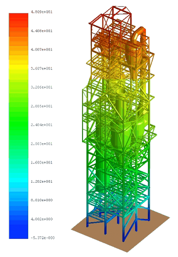
- Contour Diagrams: Create animated stress, strain, and kinematics contour diagrams for components, levels, or the whole structure filtered by the component type or material type.
- Charts: Allow users more control over all aspects of charts and the ability to animate charts to follow the steps of the analysis
- Load
- Displacement
- Stress
- Strain
- Time
- Velocity
- Acceleration
- Movie Generation: Add text and markers to .AVI and .BMP.
- Export to 3D Formats:
- Autodesk® 3D Studio Max*
- Autodesk® Maya*
- VRML*
Loads
Various static and dynamic loading scenarios can be implemented in ELS 3.1 utilizing its multi-stage sequential loading:
- Static Loading: Apply concentrated, uniform pressure, displacement, moving, and hydrostatic pressure loads.
- Dynamic Loading: Apply concentrated uniform pressure, displacement, moving, seismic, blast, impact, and hydrostatic pressure loads.
- Staged Construction & Deconstruction: Add or remove structural components during analysis.
- Initial Velocity & Acceleration: Apply velocity and/or acceleration to elements or structural component.
- Irregular Boundaries: Creates irregular boundary conditions to model natural terrain as set by the user.
- Kill Boundaries: Eliminates unwanted debris and decreases simulation time based on “killing” boundary conditions set by the user.
- Rigid Body Regions: Easily apply rigid body constraints to any elements inside a specific region in space even if the elements are not yet created.
- Spring Controller: Gives users control over the material properties of springs enclosed in any specified region.
- Loading Regions: Apply loads to all elements enclosed in a specifically defined region.
- Linear & Nonlinear Materials Models: For concrete, steel, aluminum, brick, glass, tension only, and elastic.
- Material Regions: Edit the material of all elements enclosed in a certain region.
- Physical Data Conflict Dialogue: Automatically detects conflicts in loads and boundary conditions, allowing the user to remove them.
- Custom Run: Run the analysis for specific parts of the structure or the whole structure.
- Automatic Backups: Automatically creates multiple backups of the results during analysis as set by the user. Analysis can be resumed from any of the backup files.
- Solver Controller: Pause and resume analysis as well as adjust some features of the model during the analysis based on the output.
AEM Analysis
The Applied Element Method (AEM) based solver in Extreme Loading® for Structures 3.1 is a derivative of the Finite Element Method (FEM) and the Discrete Element Method (DEM). AEM is capable of performing both linear and nonlinear analysis that follows the behavior of structures through separation, collision and collapse while automatically taking into consideration:
- Yielding of Reinforcement: Automatically calculates material strain from elastic to plastic deformation.
- Plastic Hinge Formation: automatically places plastic hinges.
- Buckling and Post-buckling: automatically calculates elastic and plastic bending under compressive loads.
- Crack Propagation: automatically calculates the location and propagation of cracks.
- Membrane Action & P-Delta Effect(P-Δ): automatically calculates the dynamic force and displacement caused by Membrane Action and the P-Delta Effect.
- Separation of Elements: automatically separates elements based on nonlinear material properties.
- Collision and Collapse: automatically calculates the collision and collapse of separated elements.


